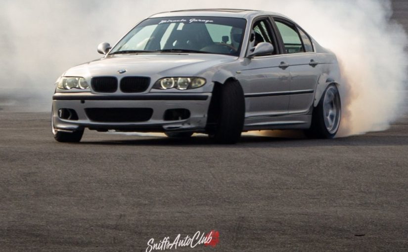
Hey, it’s been awhile since I posted something on here. In that time, I’ve made a few parts for myself and friends. I’m pretty excited about these trailing arm brackets we made for a friend’s e46. This post will dive into what the rear suspension is like on the e46, where some troubles can be, and some improvements that can be made to it.
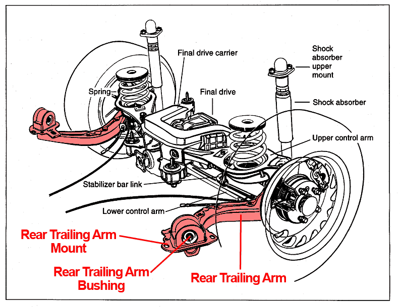 The e46 has a trailing arm with camber links rear suspension configuration. The wheel hub is rigidly mounted to the trailing arm. It has one chassis pickup point forward of the wheel that the trailing arm connects to. This pickup controls the longitudinal (front to back) movement of the wheel. There are two lateral links (upper and lower control arms) that control the lateral (side to side) movement of the wheel. The top lateral link on the e46 also has a spot for a spring to transfer the vertical wheel loads to the chassis. I really like how straightforward the suspension is on these cars. The above picture is actually from an e36 but the suspenson is very similar to the e46.
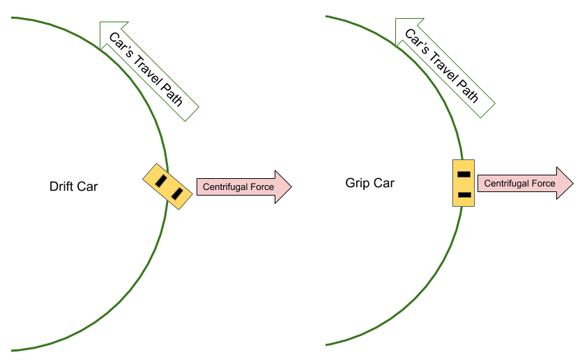 My friend had lowered his e46 and was having some alignment issues. When lowered, the camber in the rear got more negative. Most competitive drift cars have very little negative to sometimes positive rear camber because the chassis is generally rolling less compared to a grip car. This is because the car has a bunch of yaw (read: angle) in drift and physics (centrifugal force) transfers load to the outside of the turn. With drift cars, this force turns into rear weight transfer. With grip cars, this turns into side weight transfer (roll).
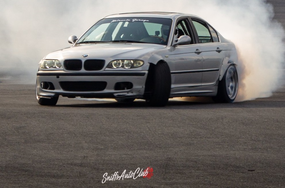 To remove camber on an e46 most people adjust the lower lateral arm inwards to pull the bottom of the wheel in towards the car. You could push the top lateral link out, but there are 2 reasons why most people adjust the lower arm.
1. Since the spring is connected to this arm, the load needs to transfer through it. This arm needs to be relatively strong. Making/buying a strong and adjustable control arm is more expensive than making/buying an adjustable 2 force member lower arm.
2. If you change the length of the arm where the spring mounts you can change the motion ratio of the spring to wheel. This could be good, but you just have to know whats going on.
 Apparent Wheel Spring Rate = Spring Rate*(Ls/Lw)^2
The ratio is squared because the wheel has 2x the mechanical advantage over the spring. The wheel pickup is further from the chassis pickup than the spring is so it has leverage. The spring pickup displacement is smaller than the wheel pickup displacement.
Pulling the lower lateral arm in removes camber but it also moves the rear of the wheel inward relative to the trailing arm mount. This adds toe out. Toe out is bad for drifting because the leading rear wheel (the one doing the most work in drift) is pointing in the direction trying to spin you out.
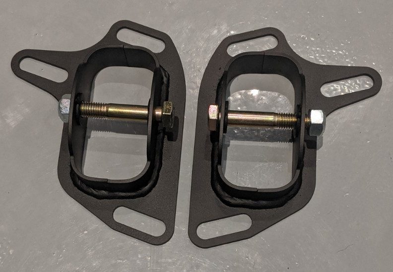 With the parts that we had, we were stuck with compromising between toe and camber. To get around this we made new parts. We made trailing arm brackets with way more adjustment over what stock allows. This allowed us to pull the front of the trailing arm inwards relative to the lateral links, giving us toe in while still maintaining the desired camber.
We made the slots so wide that these trailing arm brackets are only limited by the trailing arm pocket on the chassis (the bolt head bottoms out on the chassis).
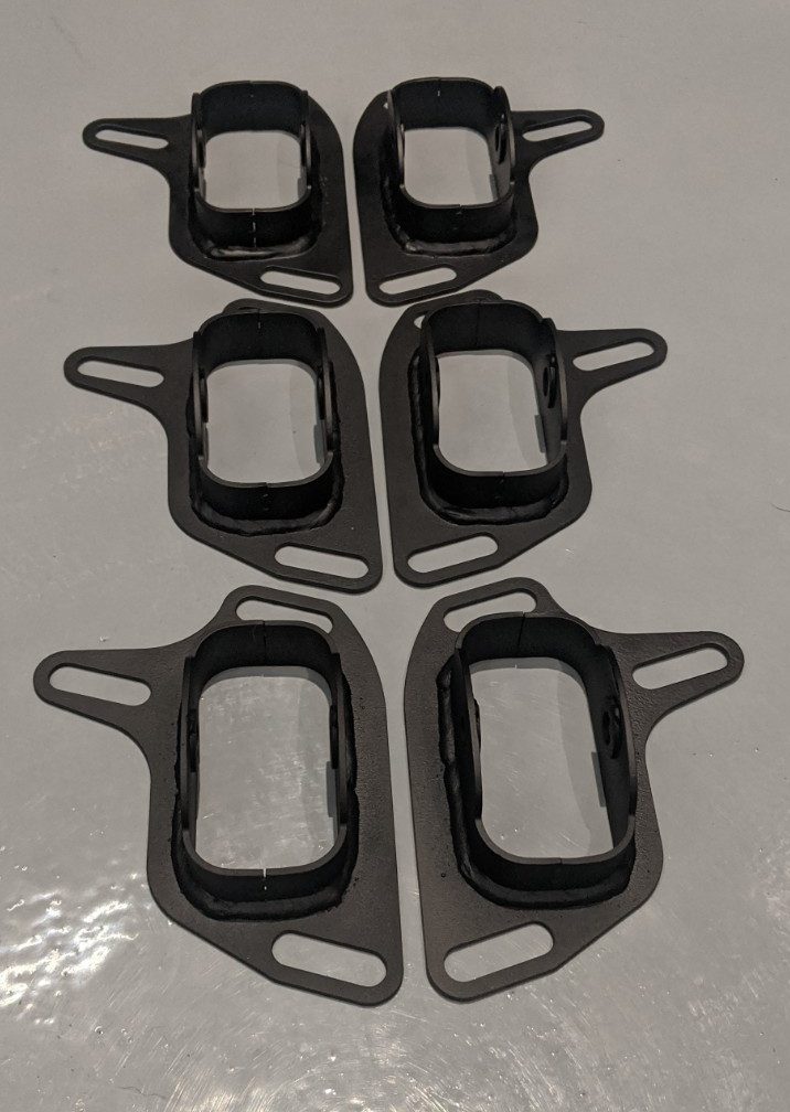 Making these was really fun because we was able to implement some large scale manufacturing techniques to small batch manufacturing. That being said, we’ve got the workflow dialed in to make more (I used this as an excuse to buy a powder coating setup). We also made the adjustment slots larger in both the toe in and out directions to solve all toe issues (cars with a lot of negative camber have the opposite problem of the competitive drift cars).
Check out the store if you want to pick yourself up a set (These will also work on e36 and z4 chassis).
